Table of Contents
- Intro
- Scene Setup
- Writing the Script
- Testing the Script
- Conclusion
Previous Tutorial: The Graph Generator
Intro
In this tutorial we'll be using the project created in the first tutorial: Project Setup, and we'll be using concepts and code covered in the previous guides.
In this guide we will cover:
- Assigning a game object to a script so it can be referenced by code.
- Accessing the components of a Game Object made in Unity
- Transforming MeshInfo instances to Z-Up
NOTE! This tutorial will show how to read basic meshes generated in Unity. When importing an OBJ or FBX file there are some more settings that need to be modified, which is discussed in the next tutorial.
Scene Setup
Up until this point, we haven't needed to interact with the Unity scene, aside from attaching a script to the Main Camera object that is placed by default. For us to demonstrate reading geometry from the scene, we will use the Unity editor to create a plane in the scene that's similar to the plane we previously created in code, but half the size.
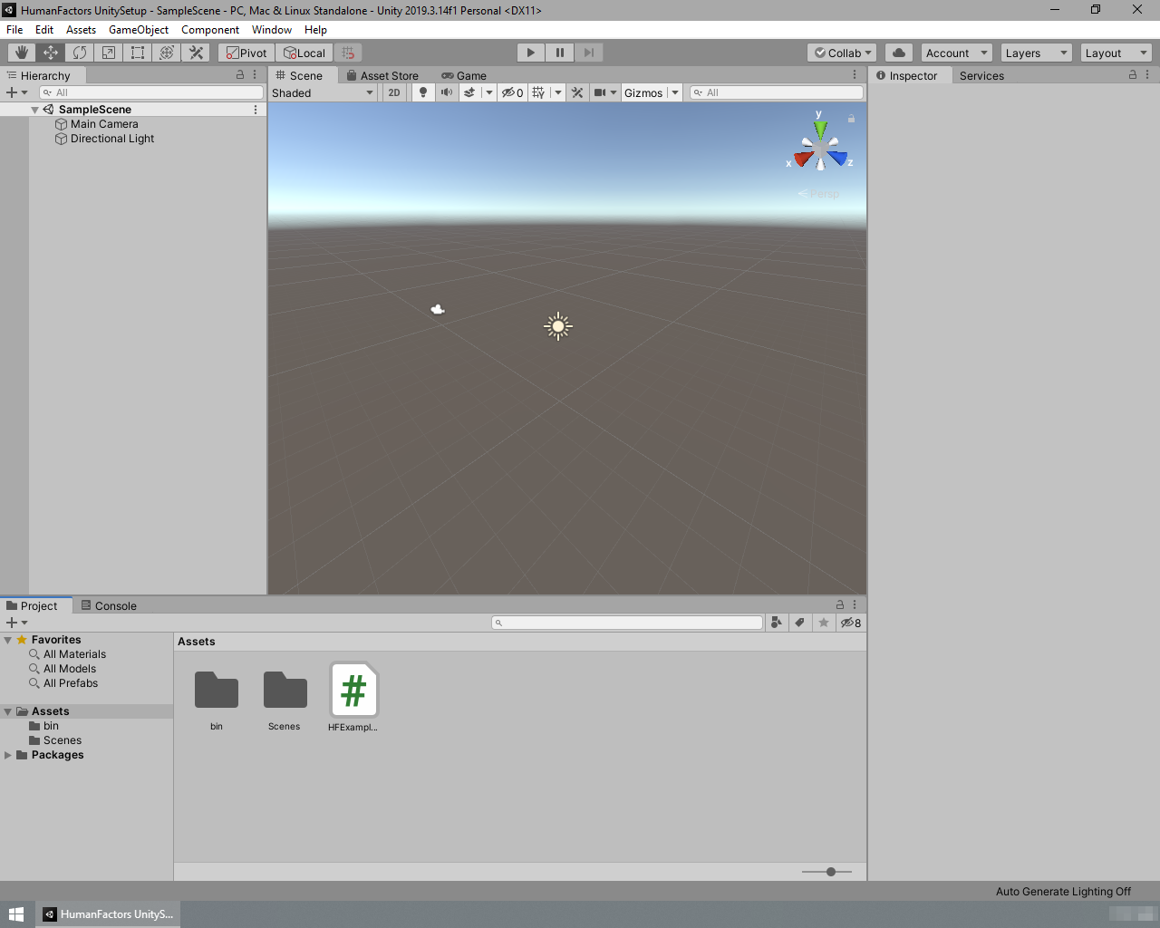
To begin, open the Unity project from Unity Project Setup.
Creating the Plane
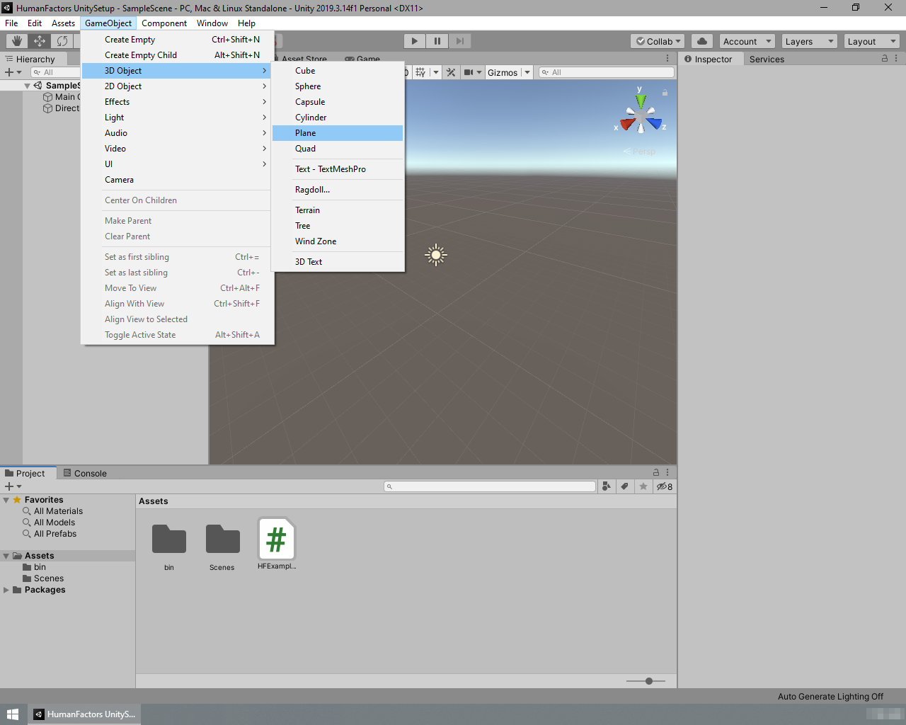
Figure 4.1: Creating a plane using the menu bar
Using the menubar at the top of the screen select GameObject > 3D Object > Plane.
Once clicked, a new 10x10 plane will be created at the center of the scene window's view. The plane we created in code was centered on the origin, but this plane isn't since it was created where the scene editor's camera was looking. We must reset this plane to the origin before moving any further.
Resetting the Plane's Position
Figure 4.2: Highlighted: The plane's x,y,z position
Left Click on the newly created plane and look at Transform header in the Inspector located at the right sidebar.
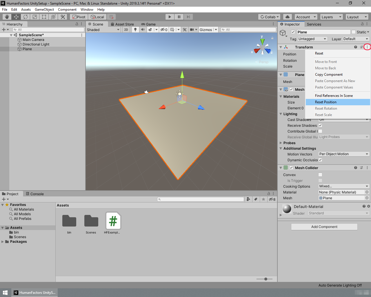
Figure 4.3: Resetting the plane's position
Under Transform you can see the plane's position, rotation and scale within the scene. To set the plane's position to the origin, left on the three dots to the right of the transform header, and select Reset Position.
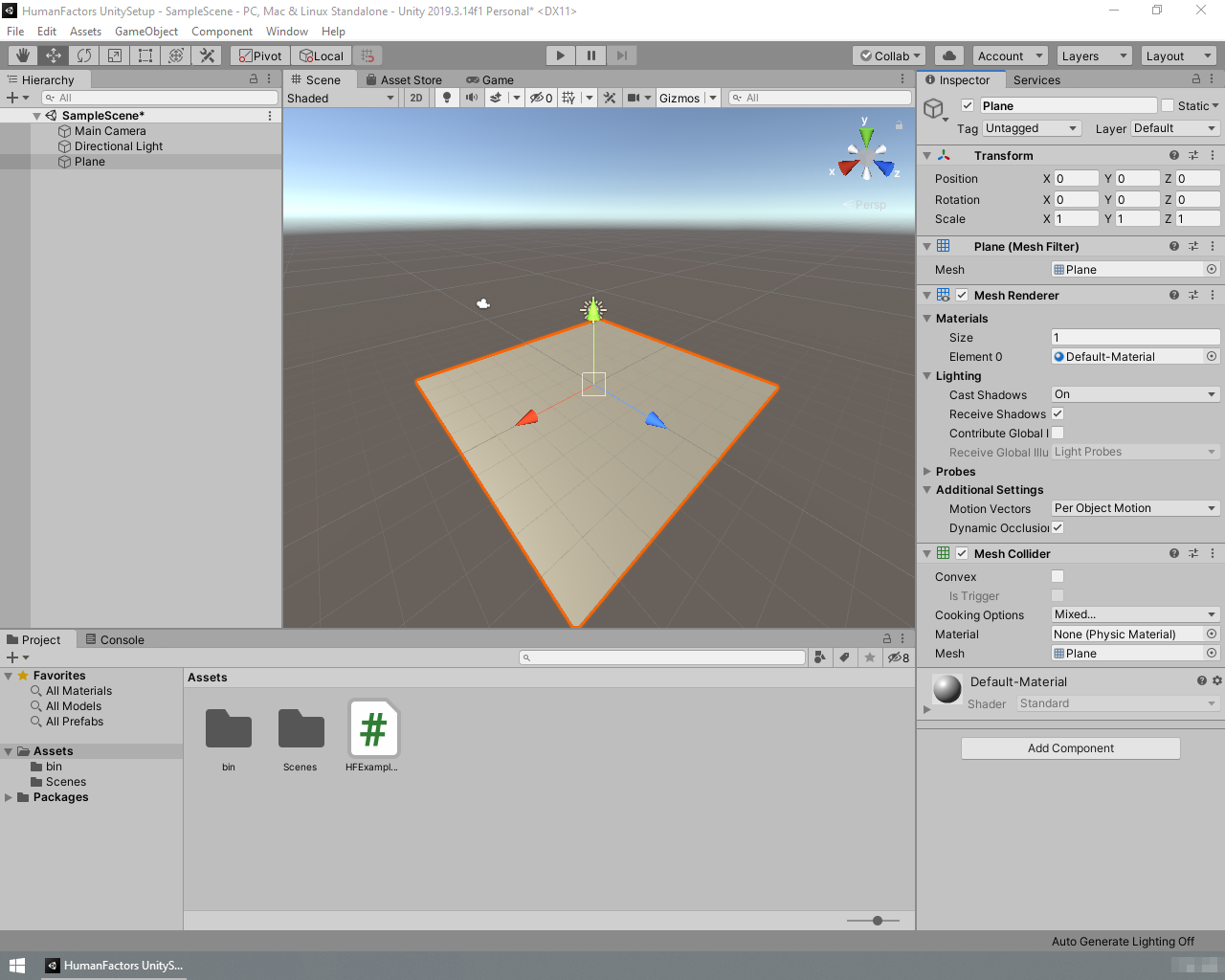
Figure 4.4: The plane centered at the scene origin
After clicking that button, your plane should be moved to the origin like in Figure 4.4. Note that the X, Y, and Z of the plane's position in the Inspector are all set to 0. Ensure that the rest of the variables in the transform header match that of Figure 4.4. Now that we have the plane ready to go, we can begin working on the script to get its vertices and triangles.
Writing the Script
 Figure 4.5 An Empty Script
Double click on HFExampleScript that we created in the first tutorial to open up Visual Studio if it isn't open already. You should see a blank page like the above. If you're coming from a previous tutorial, please clear it so it matches this.
Just like the previous tutorials, we're going to declare which namespaces this script will use in the using section. For now we only need one using declaration. Add this to the top of your script like in the previous tutorials.
Later you will be using different sections depending on whether you're generating a graph or casting a ray.
Setup for Adding References Through The Unity Inspector
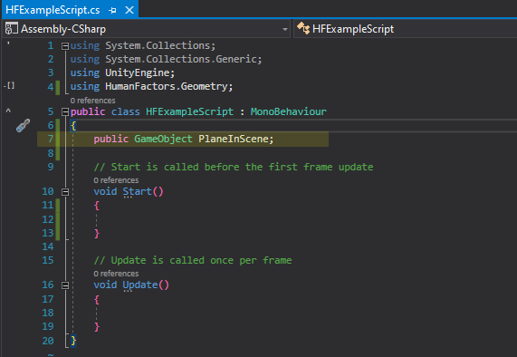
Figure 4.6: Script with a GameObject property
There are many ways to reference a GameObject in the scene from a script, but for this example we'll be setting up our script so we can select a mesh in the scene from the Unity Inspector. Add a GameObject property to the script like shown on line 7 of figure 4.6.
Later we'll use the Unity Inspector to assign the plane in the scene to this property.
Getting a Reference to the Mesh Held by a Specific GameObject
Before we can extract the triangles and vertices from one an instance of a Unity Mesh, we first need to get a reference to the Mesh itself. Doing this requires some understanding of Unity GameObjects and their components.
Background on GameObjects and Components
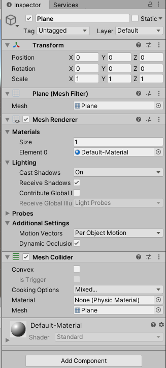
Figure 4.7: Components of the Plane shown in the Unity Inspector
Minimize Visual Studio then switch back to Unity for a moment. Left click on the plane we created previously, then look at the Inspector on the right sidebar. It should look similar to Figure 4.7. Here you can view all information about the plane, such as its position, the material it uses, which mesh it's referencing, etc. You'll notice the inspector is split into several sections: Transform, Meshfilter, Mesh Collider, and MeshRenderer. Each of these sections is a separate Component and the object we see in the scene is just a container for those components called a GameObject.
As stated in the Unity Documentation:
GameObjects are the fundamental objects in Unity that represent characters, props and scenery. They do not accomplish much in themselves, but they act as containers for Components, which implement the real functionality.
What this means for us is that the plane we see in the scene is not a Mesh, but a GameObject that contains a MeshFilter that contains a Mesh. You can think of it like GameObject > Mesh Filter > Mesh. To obtain the Mesh itself, we must get it from the MeshFilter component of the Plane GameObject.
In Practice
A game object's components can be retrieved using the GetComponent method. Go back to the Visual Studio window. In our script we will store a reference to the plane's mesh filter in a variable named PlaneFilter at the beginning of the script's Start() function like so:
Then we can access the actual mesh carried by PlaneFilter by calling its .mesh property:
Now we have the plane as a mesh and are ready to get the required info from it for DHARTAPI.
Getting the Vertices and Triangles
As previously stated, a mesh is comprised of an index and vertex array. To use this mesh in DHARTAPI, we need to construct a MeshInfo object using these arrays. Fortunately, Unity provides a straightforward way to access the triangle indices of a mesh in a format that we can use for DHARTAPI, but unfortunately the vertices only come in an array of Vector3, instead of the array of floats that we need. We will need to write a method to convert this array of Vector3 into an array of floats before we can use it in DHARTAPI.
To simplify the process of converting the vertices to a suitable format, we will add a separate method called Vector3ArrayToFloatArray that will transform the array of Vector3 into an array of float ready for DHART.
On line 9, just above the Start() function, add the following method:
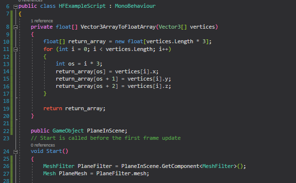
Figure 4.8: Location for Vector3ArrayToFloatArray
Now we can call this method with the mesh's vertices as input to get an array usable with DHARTAPI. Retrieve the indices and vertices from the mesh by calling its .triangles and .vertices properties, making sure to convert the array of vertices array from an array of Vector3 to an array of floats.
After that, the process of constructing an instance of MeshInfo is identical to the previous tutorials:
Before we can continue to using this mesh it's important to cover a significant difference between this mesh and the mesh we've been creating in our code.
Transforming the Mesh From Y-Up to Z-Up


Figure 4.9: Left: Unity's coordinate system. Right: DHARTAPI's Coordinate system
The Graph Generator expects geometry to be stored as if the Z-Axis were up as shown in the picture on the right. In Unity however, the Y-Axis is up, as shown in the left picture, meaning that we'll get inaccurate results if we use the mesh as is. To solve this, MeshInfo has a method RotateMesh that allows it to rotate itself after is has been constructed. Another class in the Geometry namespace titled CommonRotations contains the rotation necessary to perform this conversion.
Enter the following code to rotate the plane to the correct orientation:
Now that the plane is in the correct orientation, we are ready to move on to verifying that we loaded the mesh successfully.
Choose code From Previous Tutorial to Verify Results
Up until this point, your code should match the code below.
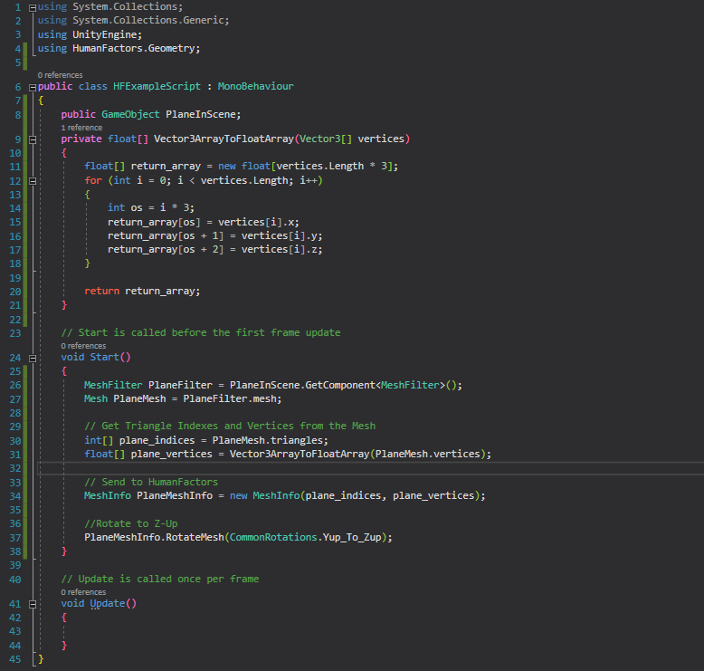
To see if we're successfully reading the mesh from the scene, pick either the graph generator or the raytracer tutorial to use for testing. Substitute PlaneMeshInfo everywhere the code from the previous tutorials use Plane. The code you take from the other sections should be added directly after the line containing PlaneMeshInfo.RotateMesh().
The lines you should copy for each tutorial are:
Graph Generator
Add the following using statments:
Copy and paste lines Lines 30 - 42 from the Graph Generator tutorial:
Ray Tracer
Add the following using statments:
Copy and paste lines 28 - 43 from the raytracer tutorial:
Make sure to copy over any other using declarations that the selected tutorial uses, since those are required for it to function. Once you've finished this, SAVE your script, minimize Visual Studio, and switch to the Unity Editor.
Testing the Script
Like in the previous tutorials, drag the HFExampleScript onto the Main Camera object in the scene hierarchy to set it as a component. In the previous scripts we were ready to go after this step, but here we need to assign the Plane GameObject to the script in the Unity Inspector.
Adding References to Properties Through the Unity Inspector
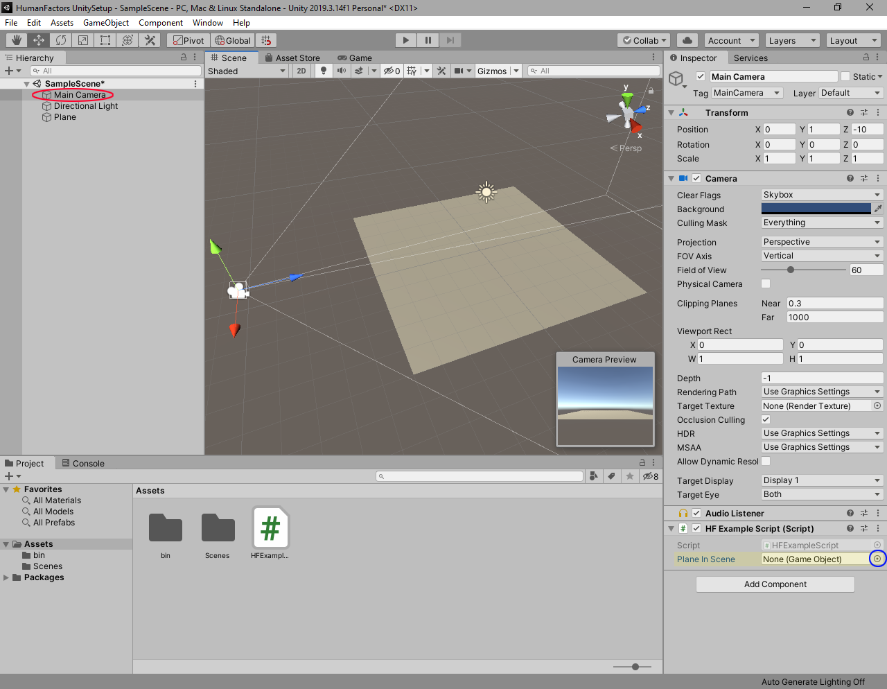
Figure 4.10: Red circle: Main Camera, Highlighted: PlaneInScene Reference, Blue Circle: Assign Reference Button
Click on the Main Camera in the left under the scene hierarchy. Notice that the HF Example Script component now has a new element under it titled Plane In Scene. This is the class member we created earlier, and we must assign it to the Plane we created. To assign the plane to this script, click the icon to the right of Plane In Scene (Circled in blue in Figure 4.10).
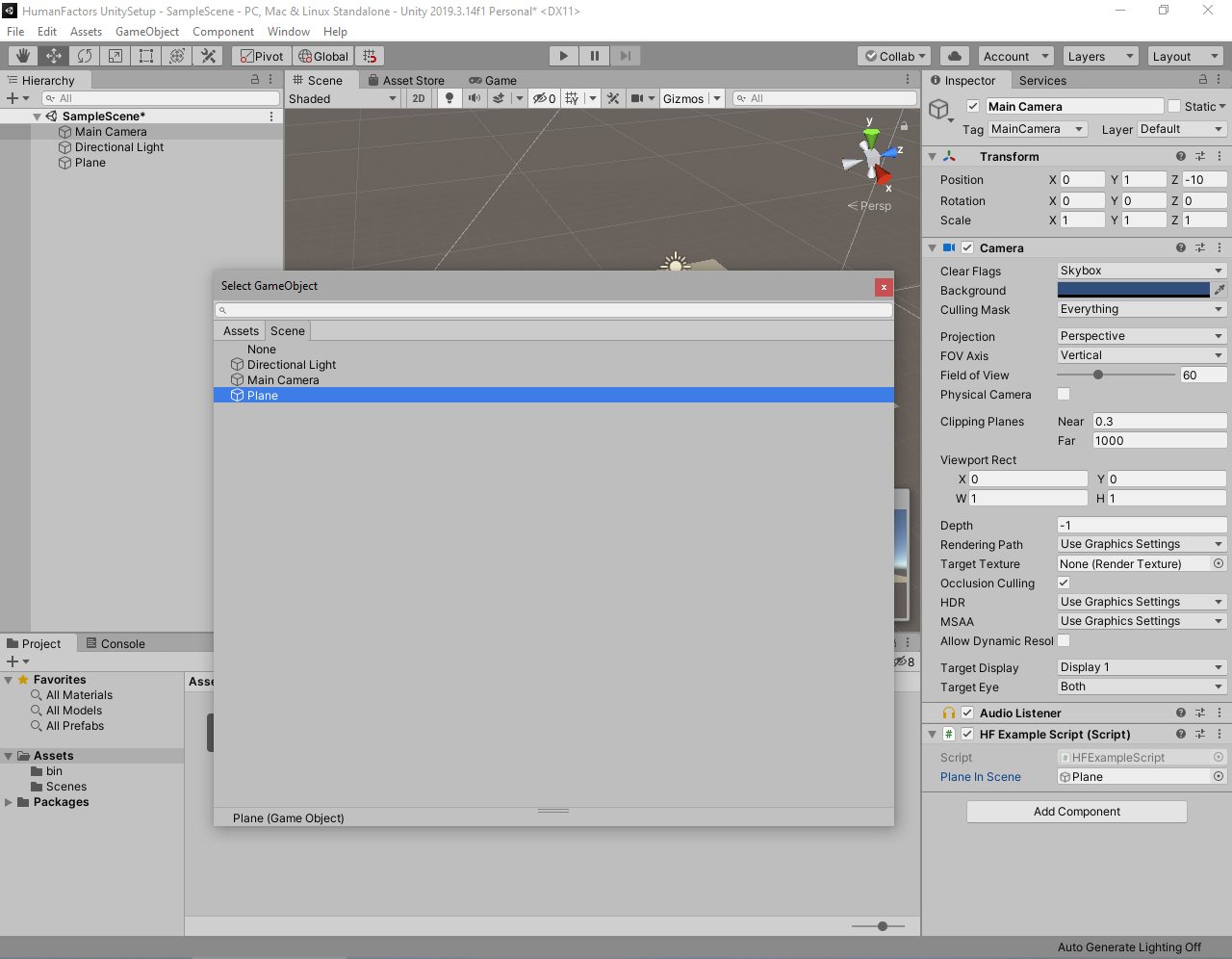
Figure 4.11: Gameobject Select Window
A new window will appear asking you to select a game object. Double click on Plane, highlighted in Figure 4.11, then look back at the Unity Inspector.
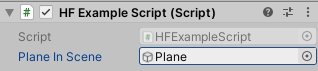
Figure 4.12: Inspector With Plane
You should now see the plane in the Unity Inspector next to PlaneInScene, like in Figure 4.12. If you see this, then you have successfully added the plane to the script as a reference.
Comparing Output
Now, enter play mode by clicking the play button. If you have performed the above steps correctly, then your output should match The output below for the code you've chosen:
Graph Generator : [(0.000,0.000,0.000), (-1.000,-1.000,0.000), (-1.000,0.000,0.000), (-1.000,1.000,0.000), (0.000,-1.000,0.000), . . . (2.000,5.000,0.000), (3.000,5.000,0.000), (4.000,-5.000,0.000), (4.000,5.000,0.000)]
Raytracer : (1,0,0)
NOTE: For the raytracer you might get an extremely low number for the Z component such as 5.960464E-08 instead of 0. This is normal, since none of the plane's vertices are exactly at whole numbers like they were in our example script. In fact, if you try to print any Vector3s like the ones returned from Mesh.vertices, they will round their components before displaying them. The nodelist returned from the graph will also round the components for every node it contains when converted to a string. Keep this in mind when reviewing results in the future.
If your output matches the above output for the code you've chosen, then you have successfully completed this tutorial.
Conclusion
Here is a link the full project created in this guide: Full Project
With this you have successfully read geometry from the Unity Scene and passed it to DHARTAPI. This concludes the tutorial series for this point.
If you want a more indepth look at using the Inspector to assign properties to components, see the Official Unity Documentation.