Table of Contents
Previous Tutorial: Project Setup | Next Tutorial: Graph Generator
Intro
Now that we know the DHARTAPI library can be referenced by our new Unity Project, let's check to see that it's working by writing a simple script that utilizes the Raytracer. Ray intersections are used internally by many of the analysis methods in DHARTAPI, and can be an extremely useful tool for analyzing space. In this tutorial we will write a script that performs the following when playmode is entered:
- Create a Plane in DHARTAPI from vertices and triangle indices.
- Cast a ray at the plane.
- Print the point where the ray intersected the plane.
This tutorial assumes that you've completed the first tutorial, since we will be using the project created in it as a base, and building upon concepts first established there. If you want to start here, you can download the full Unity project at the end of the previous tutorial.
Now, let's begin writing our script.
Writing the Script
Figure 2.1: A Blank MonoBehavior Script
In the Visual Studio window we opened in the last tutorial, look at the contents of HFExampleScript.cs. The contents should match that of Figure 2.1. Once you're sure of this, it's time to start filling it in.
NOTE: Remember, if you ever exit out of Visual Studio, you can always reopen it by double clicking a script in the assets window of the unity editor.
Using Declarations
Before getting into the logic of the script itself, we will add using declarations for the namespaces in DHARTAPI that we plan to reference.
Add the following lines to the top of the script starting at line 4.
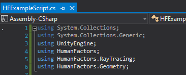
Figure 2.2: The Using declarations required for this script
Lines, 1-6 of your code should match Figure 2.2.
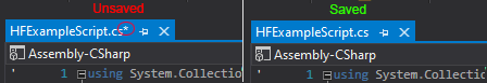
NOTE: While editing your code, you may notice the colored bar to the left between the line numbers and the code itself. This bar displays the changes you've made to the current document. When you make unsaved changes, the bar will appear and be colored yellow, then once you save it will turn green.

Figure 2.3: The body of the Start method highlighted
With using declarations in place, we'll be writing the rest of our code in the body of the Start() method beginning on line 13 (highlighted in yellow in Figure 2.3).
Creating a Plane
Now we will create a plane for our ray to intersect. Every mesh is, at minimum, comprised of two arrays:
- An array of floats containing the (x,y,z) location of every vertex in the mesh.
- An array of integers containing the indices for each triangle or "face" of the mesh.
A plane is comprised of four vertices, and two triangles. Here are the vertex and index arrays for a 10x10 plane on the xy plane.
In the index and vertex array, every 3 elements represent a separate triangle or vertex respectively. So, the first vertex is at location (-10,10,0) and the first triangle is comprised of the fourth, second, and first vertices. For more information on what both arrays mean, see out the [MeshInfo Documentation]().
TODO: Replace the empty links with links to our documentation.
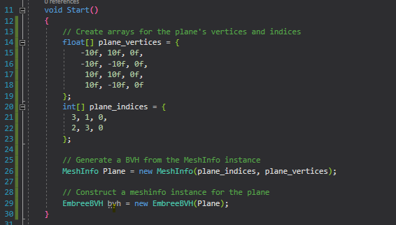
We will use these arrays to construct a new MeshInfo object in DHARTAPI. Call the MeshInfo constructor with the two arrays we defined above as arguments.
Before we can use this geometry with the Raytracer, we must first generate a Bounding Volume Hierarchy, or BVH using the geometry as input. In short, a BVH is an accelerated data structure that drastically reduces the time required to perform ray intersections. You can read more about the BVH in its dedicated article [Bounding Volume Hierarchy]().
To generate a BVH from an instance of MeshInfo, call the BVH constructor with the MeshInfo instance as an argument.
At this point, your start function should match the following code:
With the BVH created, we're ready to call the Raytracer and cast a ray.
Casting a Ray
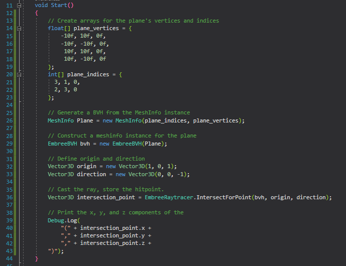
We'll put the origin point of the ray at (1,0,1) and cast it in the direction (0,0,-1). This should intersect with the plane we defined earlier at the point (1,0,0). In the start method, just below the line we create the BVH, define an origin point and a direction for the ray.
Depending on which function you call, the EmbreeRaytracer can return 3 different types of information:
- The coordinates where a ray intersected the mesh.
- The distance from the ray's origin to the point where it intersected the mesh
- A boolean true/false for whether the ray intersected the mesh at any point.
For this guide we will use [IntersectForPoint]() to get the point where the ray intersects the mesh. Starting on line 35 call the EmbreeRayTracer's IntersectForPoint function with the bvh, origin and direction as arguments.
Finally, log the point of intersection to Unity's console using Debug.Log() so we can view the results.
Here's all of that together:
Wrapping Up
Here is the final script we've been building in this tutorial.
Once you've verified your code matches, make sure to save the script by clicking File then Save in the top menu or pressing Ctrl + S on your keyboard. Unity will NOT be able to use the script unless you save it. If you're unsure, the bar on the left-hand side between your code and the line numbers should be solid green, and the title of your assembly should not have an asterisk next to it.
Testing
Now that we have a usable script, we need to attach it to some game object in order to run it. Let's minimize the Visual Studio window and go back to the Unity Editor.
Adding the script to the camera
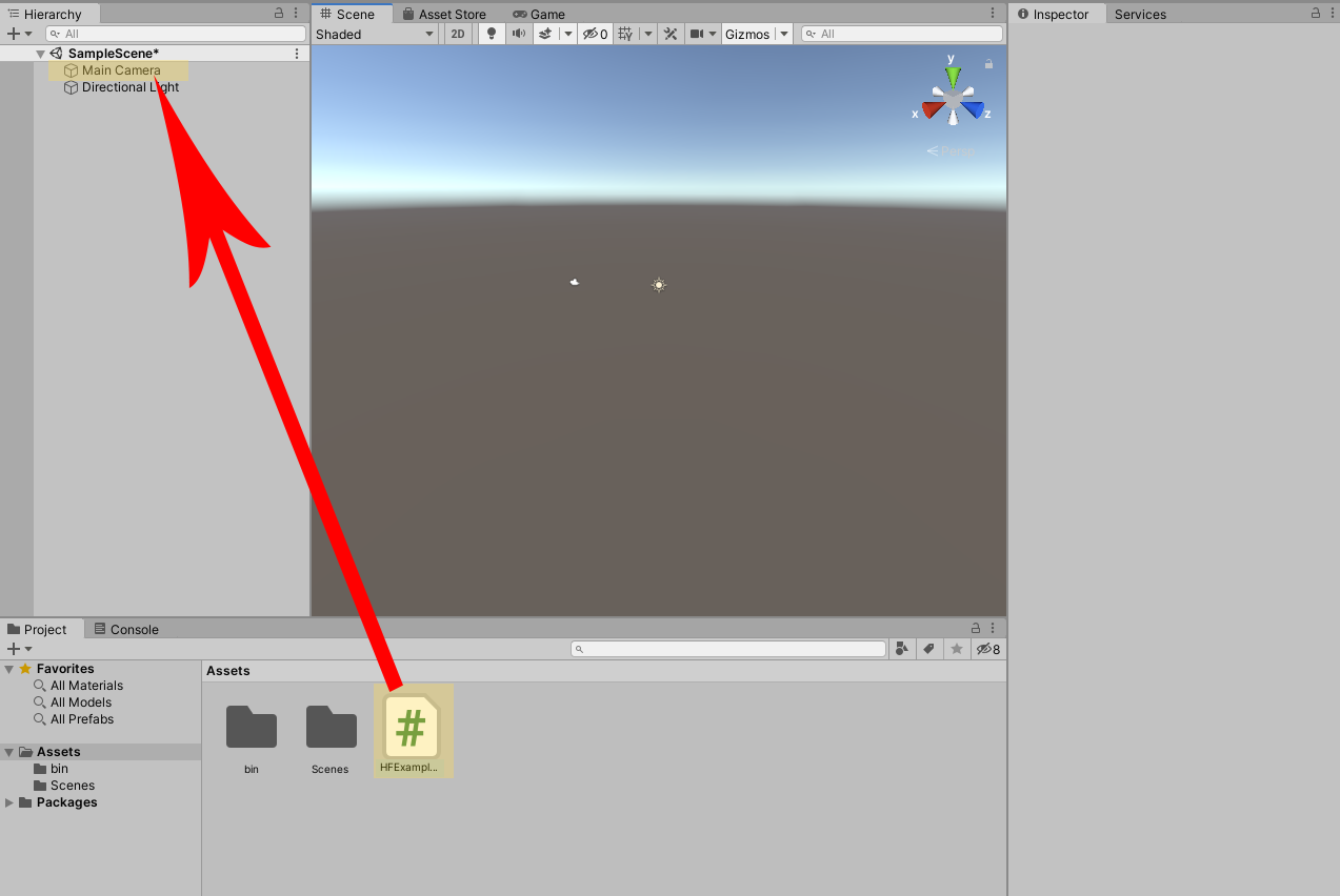
Figure 2.4 Adding HFExampleScript to the camera as a component
In the Unity window drag HFExampleScript.cs to Main Camera in the scene hierarchy like shown in Figure 2.4. After doing this, it may appear as if nothing happened, but by dragging HFExampleScript over the camera you've added HFExampleScript to the camera as a component.
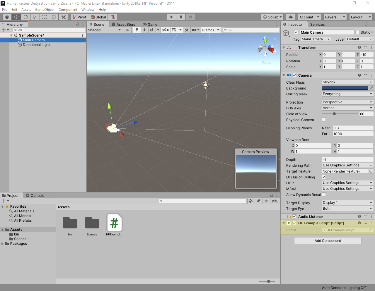
Figure 2.5 Viewing the components of the Main Camera
You can verify that the script has been added to the camera by left clicking the camera in the scene hierarchy and looking at its components in the Inspector on the right sidebar. At the bottom of the Inspector you should see a header for HF Example Script like the one highlighted in Figure 2.5. Once you've made sure it exists, you can click on an empty space in the scene view to deselect the camera.
NOTE: If you don't see the inspector in the right sidebar, you can enable it by selecting Window > General > Inspector from the top menubar.

NOTE: If you notice multiple copies of the script in the Inspector, you can remove duplicates by left clicking on the rightmost side of header for the duplicate components' headers, then clicking Remove Component.
>
Executing the Script
Now that we've set HFExampleScript as a component of the Main Camera, its Start() function containing our code will run when the editor enters play mode.
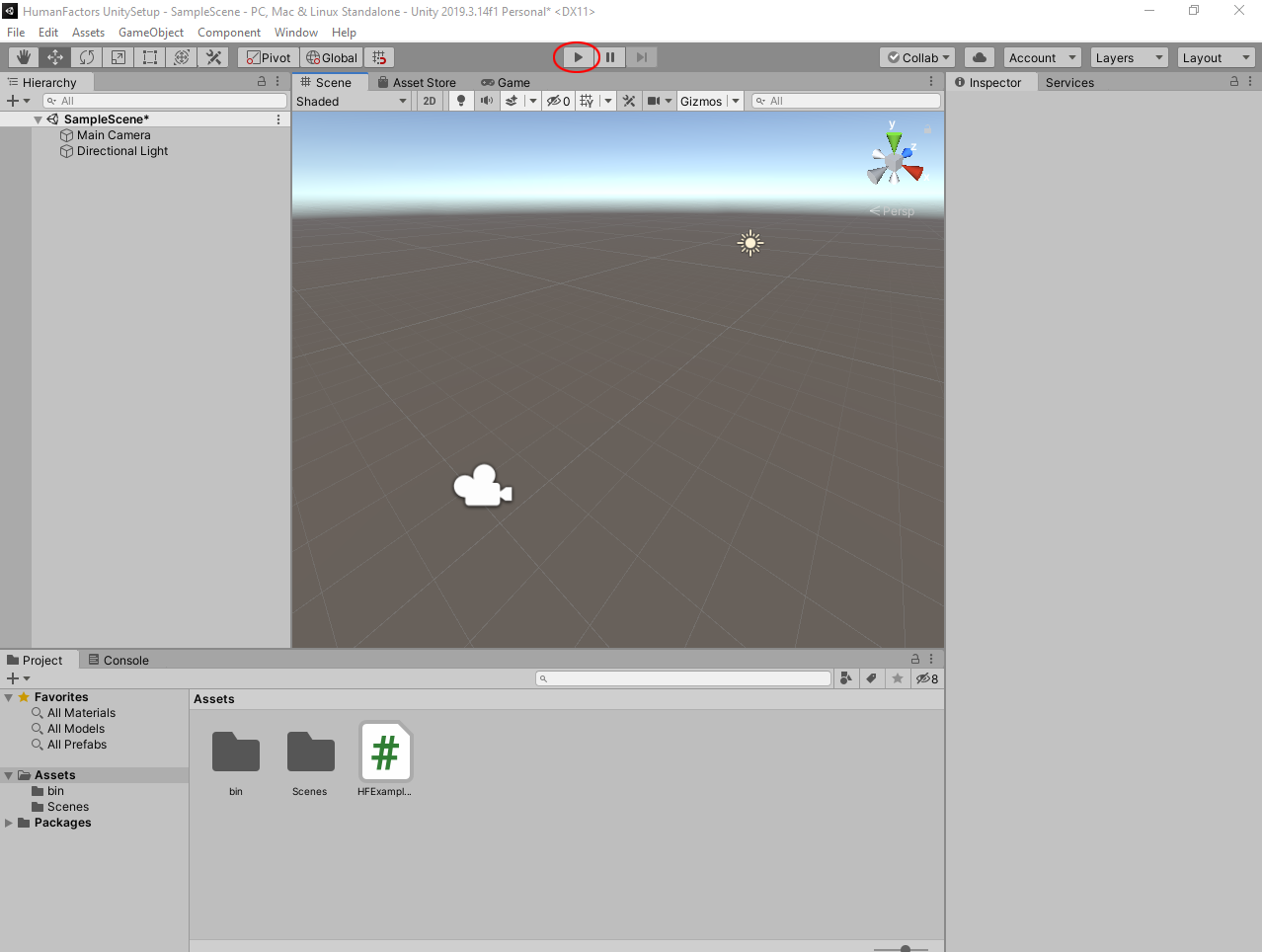
Figure 2.6 Circled play button in editor window
To enter playmode, press the play button located at the top center of your screen, circled in red in Figure 2.6. Once clicked, you will enter play mode, indicated by the play button turning blue.
NOTE: If when entering play mode, the game window becomes full screen like below, that means you have the Maximize On Play option enabled. You can disable it by pressing the Maximize On Play button circled in red below. For this tutorial series, we will leave this option off since it hides the console.
>
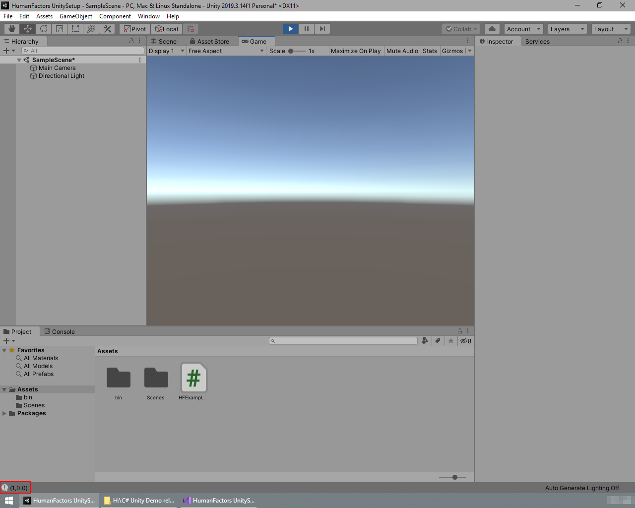
Figure 2.7A Intersection Results in play mode.
Figure 2.7B Results from 2.7A magnified
If everything went right, after entering play mode the console located at the bottom of your editor's window should show (1,0,0), which is the exact point where the ray intersected the plane. Figure 2.7B is a magnified version of the console's output enclosed by the red box shown in 2.7A.
NOTE: If you see no output at all, that means your version of Unity has log messages disabled. To enable log messages click on the Console tab just above the assets window to open the console.
After this, you should notice the three buttons in the top right of the console window. The Left most button with an exclamation point in a speech bubble should be greyed out. Click on this button to enable log messages.
You will see your output in the space where the assets tab occupied, instead of the bottom bar. You can switch back to the assets window by clicking the project tab to the left of the console tab.
Future calls to
Debug.Log()will appear at the bottom of the screen like shown in Figure 2.4.
If your console's output matches, then you've successfully completed this tutorial. You can press the play button again to exit playmode.
Conclusion
Full project Link: Tutorial 2: Casting a Ray at A Plane
In this tutorial we've successfully created a plane from an array of vertices and triangle indexes, then casted a ray at it, then found the point where the ray and the plane intersected. Through this we've gained some experience using Visual Studio with Unity and became more familiar with the Editor's UI. In the next tutorial we will build upon this experience to cover a core part of the DHARTAPI Library: The Graph Generator.